Multi-Cluster Load Balancing with GKE
One of the features I like the most about GCP is the external HTTP(S) Load Balancing. This is a global load balancer which gives you a single anycast IP address (no DNS load balancing needed, yeey!). Requests enter the Google’s global network at one of the edge points of presence (POPs) close to the user,11. Over 90 locations around the world - Load Balancing - Locations and are proxied to the closest region with available capacity. This results in highly available, globally distributed, scalable and fully managed load balancing setup. It can be further augmented with DDoS and WAF protection Cloud Armor, Cloud CDN or Identity-Aware Proxy (IAP) to secure access to your web applications.
With this, multi-cluster load balancing with GKE immediately comes into mind and is often a topic of interest from clients. And while there’s no native support in GKE/Kubernetes at the moment,22. Leaving the Anthos aside for now. Anthos is application management platform that enables you to run K8s clusters on-prem and in other clouds, and also extends functionality of GKE Clusters, incl. multi-cluster ingress controller.) GCP provides all necessary building blocks to set this up yourself.
Let’s get familiar with the GCP Load Balancing components in the first part. We will follow the journey of a request as it enters the system and understand what each of the load balancing building blocks represents. And we will setup load balancing across two GKE clusters step by step in the second part.
GCP Load Balancing Overview
Fig. 1: GCP Load Balancing Overview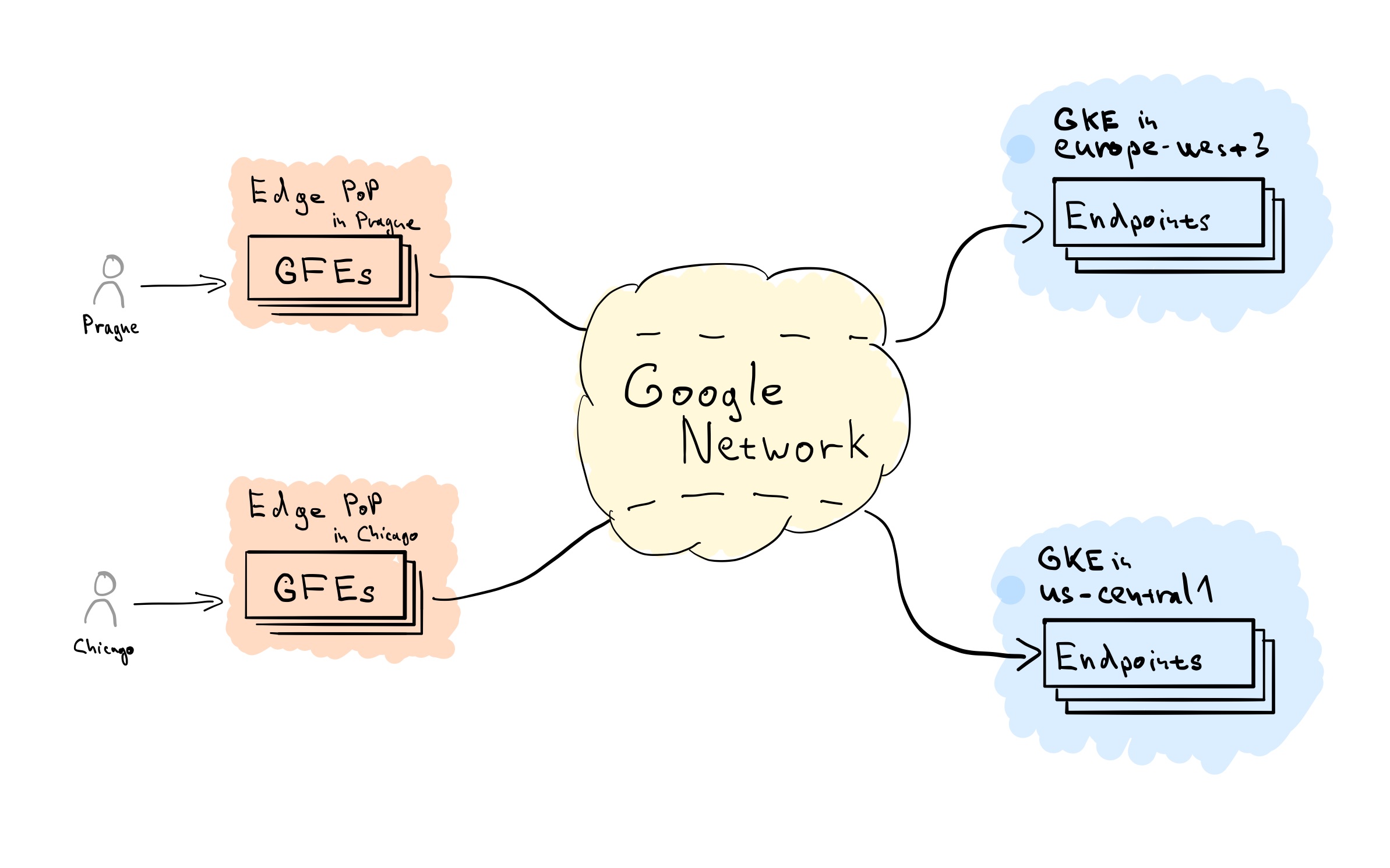

Let’s start with a high-level Load Balancing flow overview. HTTP(S) connection from client is terminated at edge location by Google Front Ends (GFEs),33. GFEs are software-defined, scalable distributed systems located at Edge POPs. based on HTTP(S) Target Proxy and Forwarding Rule configuration. The Target Proxy consults associated URL Map and Backend Service definitions to determine how to route traffic. From the GFEs a new connection will be established, and traffic flows over the Google Network to the closest healthy Backend with available capacity. Traffic within the region is then distributed across individual Backend Endpoints, according to their capacity.
GCP Load Balancing Components
Fig. 2: GCP Load Balancing Components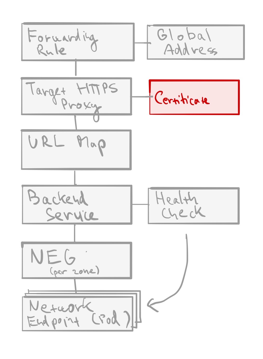

Forwarding Rule - each rule is associated with a specific IP and port. Given we’re talking about global HTTP(S) load balancing, this will be anycast global IP address (optionally reserved static IP). The associated port is the port on which the load balancer is ready to accept traffic from external clients.44. The port can be 80 or 8080 if the target is HTTP proxy, or 443 in case of HTTPS proxy
Target HTTP(S) Proxy - traffic is then terminated based on Target Proxy configuration. Each Target Proxy is linked to exactly one URL Map (N:1 relationship). You’ll also have to attach at least one SSL certificate and configure SSL Policy In case of HTTPS proxy.
URL Map - is the core traffic management component and allows you to route incoming traffic between different Backend Services (incl. GCS buckets). Basic routing is hostname and path based, but more advanced traffic management is possible as well - URL redirects, URL rewriting and header- and query parameter-based routing. Each rule directs traffic to one Backend Service.
Backend Service - is a logical grouping of backends for the same service and relevant configuration options, such as traffic distribution between individual Backends, protocols, session affinity or features like Cloud CDN, Cloud Armor or IAP. Each Backend Service is also associated with a Health Check.
Health Check -determines how are individual backend endpoints checked for being alive, and this is used to compute overall health state for each Backend. Protocol and port have to be specified when creating one, along with some optional parameters like check interval, healthy and unhealthy thresholds or timeout. Important bit to note is that firewall rules allowing health-check traffic from a set of internal IP ranges55. For External HTTP(S) Load Balancing these ranges are
35.191.0.0/16and130.211.0.0/22. must be in place.Backend - represents a group of individual endpoints in given location. In case of GKE our backends will be Network Endpoint Groups (NEGs),66. Network endpoint groups overview one per each zone of our GKE cluster (in case of GKE NEGs these are zonal, but some backend types are regional).
Backend Endpoint - is a combination of IP address and port, in case of GKE with container-native load balancing77. Container-native load balancing requires cluster in VPC-native mode and allows load balancers to target individual Pods directly (as opposed to targeting cluster nodes). pointing to individual Pods.
Setup:
We will set up multi-cluster load balancing for two services - Foo and Bar - deployed across two clusters (fig. 3). We’ll use simple path-based rules, and route any request for /foo/* to service Foo, resp. /bar/* to service Bar.
Fig. 3: GKE Multi-Cluster Foo Bar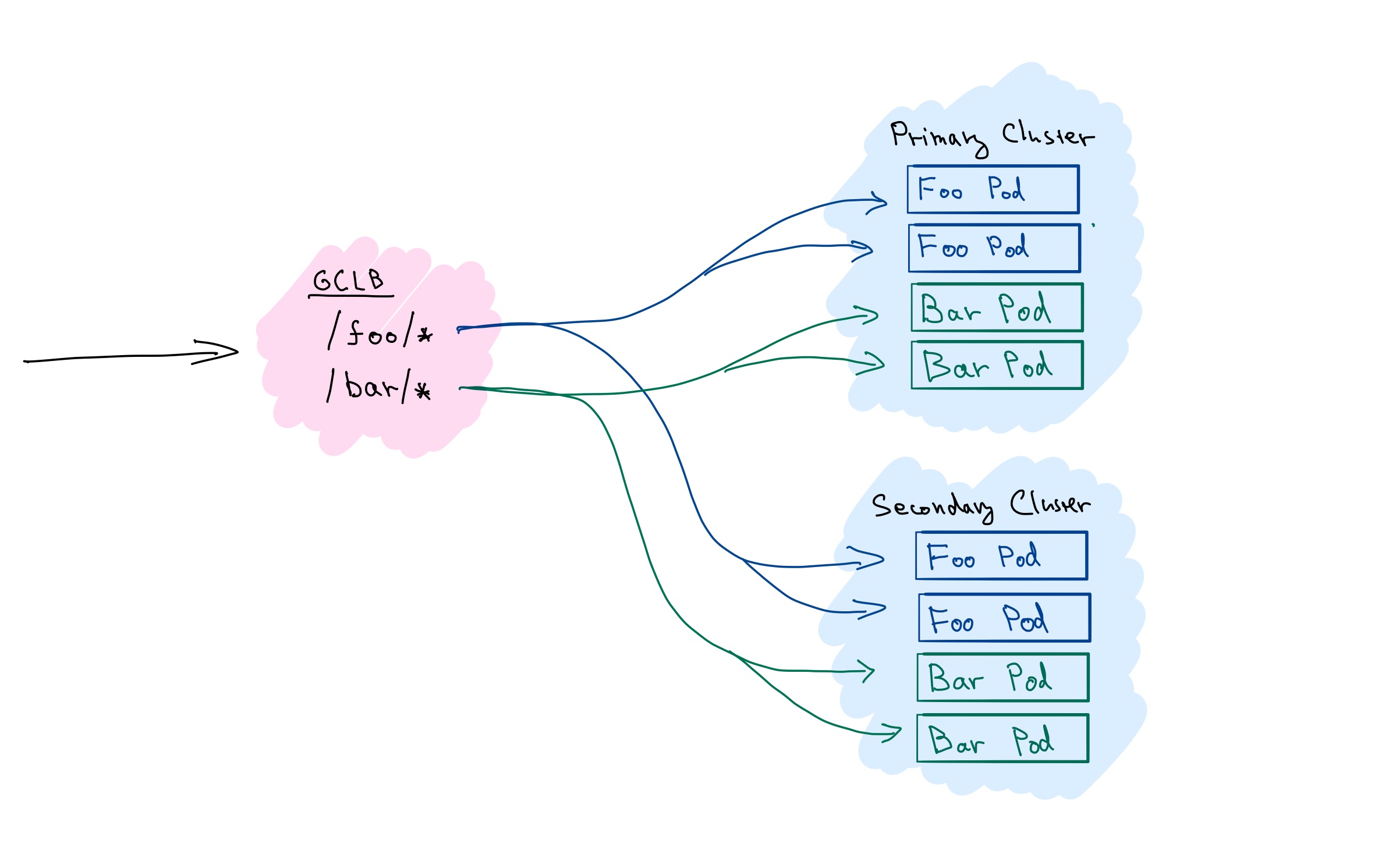

Prerequisites
- 2 GKE Clusters, in VPC-native mode, let’s call them primary and secondary88. Using clusters in different regions is more interesting.
- DNS record to point to the static IP
- Recent version of gcloud CLI
- Clone of the stepanstipl/gke-multi-cluster-native repository99. All the files referenced in the commands in this post are relative to the root of this repository.
1
2
3
$ git clone https://github.com/stepanstipl/gke-multi-cluster-native.git ... $ cd gke-multi-cluster-native
Deploy Applications and Services to GKE clusters
Let’s start by deploying a simple demo applications to each of the clusters. The application displays details about serving cluster and region, and source code is available at stepanstipl/k8s-demo-app.
Repeat following steps for each of your clusters.
Get Credentials for kubectl:
1
2
gcloud container clusters get-credentials [cluster] \ --region [cluster-region]Deploy Both Foo & Bar Applications:
1
2
kubectl apply -f deploy-foo.yaml kubectl apply -f deploy-bar.yamlYou can verify that Pods for both services are up and running by
kubectl get pods.Create K8s Services for Both Applications:
1
2
kubectl apply -f svc-foo.yaml kubectl apply -f svc-bar.yamlNote the
cloud.google.com/neg: '{"exposed_ports": {"80":{}}}'annotation on the services telling GKE to create a NEG for the Service.
You can verify services are setup correctly by forwarding local port using the kubectl port-forward service/foo 8888:80 and accessing the service at http://localhost:8888/.
Now don’t forget to repeat the above for all your clusters.
Setup Load Balancing (GCLB) Components
Create Health Check:
1
2
3
gcloud compute health-checks create http health-check-foobar \ --use-serving-port \ --request-path="/healthz"Create Backend Services
Create backend service for each of the services, plus one more to serve as default backend for traffic that doesn’t match the path-based rules.
 1
 2
 3
 4
 5
 6
 7
 8
 9
10
gcloud compute backend-services create backend-service-default \ --global gcloud compute backend-services create backend-service-foo \ --global \ --health-checks health-check-foobar gcloud compute backend-services create backend-service-bar \ --global \ --health-checks health-check-foobarCreate URL Map:
1
2
3
gcloud compute url-maps create foobar-url-map \ --global \ --default-service backend-service-defaultAdd Path Rules to URL Map:
1
2
3
4
5
gcloud compute url-maps add-path-matcher foobar-url-map \ --global \ --path-matcher-name=foo-bar-matcher \ --default-service=backend-service-default \ --backend-service-path-rules='/foo/*=backend-service-foo,/bar/*=backend-service-bar'Reserve Static IP Address:
1
2
3
gcloud compute addresses create foobar-ipv4 \ --ip-version=IPV4 \ --globalSetup DNS:
Point your DNS to the previously reserved static IP address. Note the IP address you have requested:
1gcloud compute addresses list --globalCreate an A record
foobar.[your_domain_name]pointing to this IP. You can use Cloud DNS to manage the record, or any other service of your choice. This step should be completed before moving forward1010. The DNS record needs to be in place for the Google-managed SSL certificate provisioning to work. If not, the certificate might be marked as permanently failed (as the Certificate Authority will fail to sign it) and will need to be recreated..Create Managed SSL Certificate:
1
2
gcloud beta compute ssl-certificates create foobar-cert \ --domains "foobar.[your_domain_name]"Create Target HTTPS Proxy:
1
2
3
gcloud compute target-https-proxies create foobar-https-proxy \ --ssl-certificates=foobar-cert \ --url-map=foobar-url-mapCreate Forwarding Rule:
1
2
3
4
5
gcloud compute forwarding-rules create foobar-fw-rule \ --target-https-proxy=foobar-https-proxy \ --global \ --ports=443 \ --address=foobar-ipv4Verify TLS Certificate:
The whole process of certificate provisioning can take a while. You can verify its status using the:
1gcloud beta compute ssl-certificates describe foobar-certThe
managed.statusshould becomeACTIVEwithin the next 60 minutes or so, usually sooner, if everything was setup correctly.
Connect K8s Services to the Load Balancer
GKE has provisioned NEGs for each of the K8s services deployed with the cloud.google.com/neg annotation. Now we need to add these NEGs as backends to corresponding backend services.
Retrieve Names of Provisioned NEGs:
1
2
kubectl get svc \ -o custom-columns='NAME:.metadata.name,NEG:.metadata.annotations.cloud\.google\.com/neg-status'Note down the NEG name and zones for each service.
Repeat for all your GKE Clusters.
Add NEGs to Backend Services:
Repeat following for every NEG and zone from both clusters. Make sure to use only NEGs belonging to the Foo service.
1
2
3
4
5
6
gcloud compute backend-services add-backend backend-service-foo \ --global \ --network-endpoint-group [neg_name] \ --network-endpoint-group-zone=[neg_zone] \ --balancing-mode=RATE \ --max-rate-per-endpoint=100And same for Bar service, again repeat for both clusters, every NEG and zone:
1
2
3
4
5
6
gcloud compute backend-services add-backend backend-service-bar \ --global \ --network-endpoint-group [neg_name] \ --network-endpoint-group-zone=[neg_zone] \ --balancing-mode=RATE \ --max-rate-per-endpoint=100Allow GCLB Traffic:
1
2
3
4
5
6
gcloud compute firewall-rules create fw-allow-gclb \ --network=[vpc_name] \ --action=allow \ --direction=ingress \ --source-ranges=130.211.0.0/22,35.191.0.0/16 \ --rules=tcp:8080Verify Backends Are Healthy:
1
2
gcloud compute backend-services get-health --global backend-service-foo gcloud compute backend-services get-health --global backend-service-barYou should typically see 6 backends (3 per cluster,1111. Assuming you have used regional clusters, each deployed across 3 zones, otherwise adjust accordingly. 1 per each zone) for each backend service, with
healthState: HEALTHY. It might take a while before all the backends are healthy after adding the firewall rules.
Test Everything’s Working
Curl your DNS name https://foobar.[your-domain] (or open in the browser). You should get 502 for the root, as we didn’t add any backends for the default service.
| |
Now curl paths for individual services https://foobar.[your-domain]/foo/ or https://foobar.[your-domain]/bar/ and you should receive 200 and content from the corresponding service.
| |
If you retry a few times, you should see traffic served by different Pods and Clusters.1212. If you have clusters in different regions, GCLB will prefer to serve the traffic from the one closer to the client, so do not expect traffic to be load-balanced equally between regions.
If you simulate some traffic, for example using one of my favourite CLI tools vegeta, you can nicely observe traffic distribution across backends in the GCP Console. Go to Network services -> Load balancing section -> select your load balancer -> Monitoring tab and select corresponding backend. You should see a dashboard similar to fig. 5.
Fig. 5: GKE Console - Load Balancing (both cluster were in the same region, therefore traffic is load-balanced equally across all backends)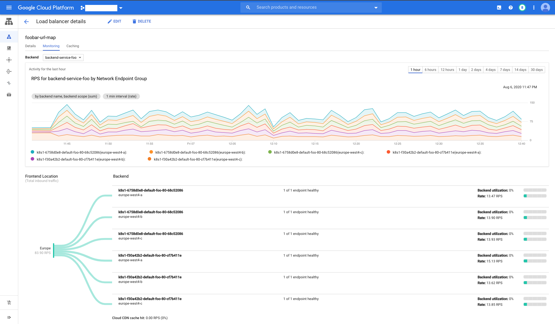

Now it’s a good time to experiment a bit. Let’s see what happens if you have clusters in a same region, and what if they’re in different regions. Increase the load and see the traffic overflow to another region (hint: remember the --max-rate-per-endpoint used before?). See what happens if you take one of the clusters down. And can you add a 3rd cluster in the mix?
(optional) gke-autoneg-controller
Notice the anthos.cft.dev/autoneg annotation on the K8s Services. It is not needed for our setup, but optionally you can deploy gke-autoneg-controller1313. I’ll not go into the details on how to deploy and use here, please follow the readme, but basically add annotation with the name of the NEG to your service, e.g. anthos.cft.dev/autoneg: '{"name":"autoneg_test", "max_rate_per_endpoint":1000}'. to your cluster, and use it to automatically associate NEGs created by GKE with corresponding backend services. This will save you some tedious manual work.
Good Job!
And that is it. We have explained purpose of individual GCLB components and demonstrated how to set up multi-cluster load balancing between services deployed in 2 or more GKE clusters in different regions. For a real life use I would recommend to automate this setup with a configuration management tool, such as Terraform.
This setup both increases your service availability, as several independent GKE clusters serve the traffic, and also lowers your latency. In case of HTTPS the time to first byte is shorter, as the initial TLS negotiation happens at the GFE server close to the user. And with multiple clusters, the request will be served by the closest one to the user.
Please let me know if you find this useful and any other questions you might have, either here or at @stepanstipl. 🚀🚀🚀 Serve fast and prosper!
